Generator
SAFETY FIRST: Protective gloves and eyewear are recommended at this point.
Removal
Remove the fairings. See the Fairings topic for more information.
Remove the fuel tank. See the Fuel Tank topic for more information.
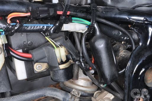


Free the generator wire bands from the frame.
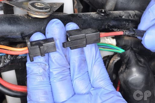
Unplug the generator connector.


Free the lower wire band from the generator wires. Move the generator wires out of the frame.
Remove the countershaft sprocket cover. See the Countershaft Sprocket topic for more information.


Remove the three generator mounting bolts with a 12 mm socket.
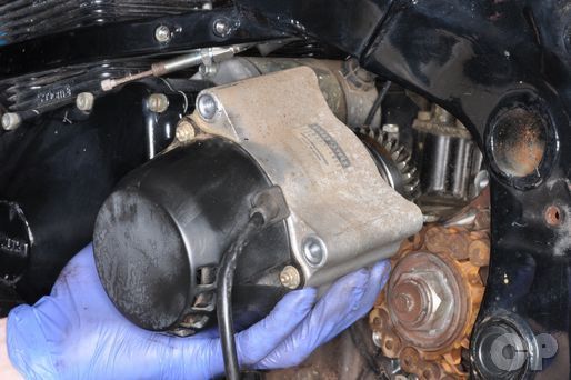
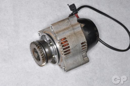
Remove the generator from the crankcase.
Disassembly
Inspect the generator O-ring. Replace it as needed.


Hold the generator driven gear in a soft jawed vise and loosen the nut. Remove the nut and washer.


Remove the generator driven gear and the four damper pieces.


Using a universal puller tool remove the damper housing from the generator shaft. Use caution here because the damper will pop of with force.
Special Tool-Bearing Puller
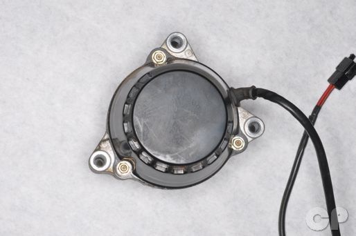


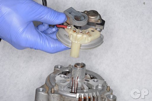
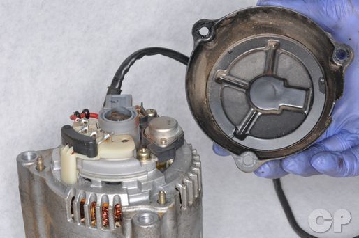
Loosen the three generator cover nuts with an 8 mm socket. Remove the nuts and the cover.
The stator coil wires are connected to the rectifier with solder.
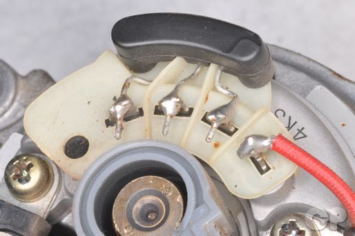


Use a soldering iron to free the stator coil lead wires.
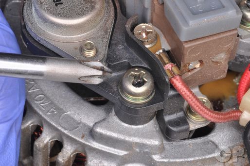


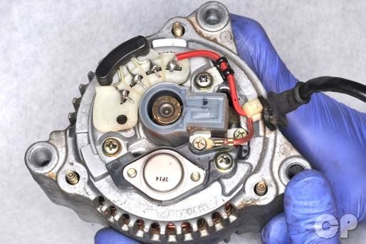
Remove the three regulator mounting screws with a #2 Phillips screwdriver.


Remove the rectifier cover. Make sure the stator coil lead wires are free.
Slide the brush holder, IC regulator, and rectifier off of the generator.


To separate the IC regulator from the rectifier separate the wire from the rectifier terminal with a soldering iron.


Remove the three bearing retainer screws with a #2 Phillips screwdriver.


Pry the generator housing half apart with three flat blade screwdrivers. Do not use a hammer to separate the housing.
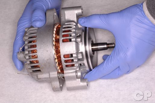


Remove the housing from the generator.


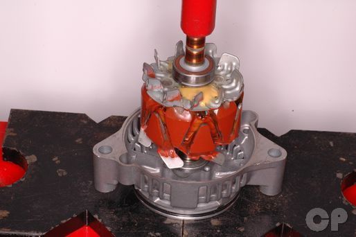
To remove the generator shaft and rotor from the inner housing it must be pressed out. Our shaft was seized on the bearing and when the shaft was pressed out the bearing came out with it and destroyed the bearing retainer.
Bearings


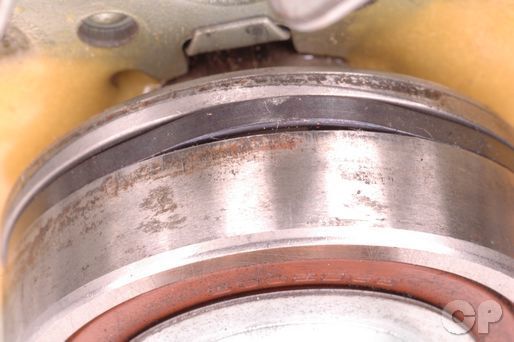
Inspect the bearing by turning it with a finger. the bearing should turn smoothly without noise or excessive play. Replace the bearing if needed.


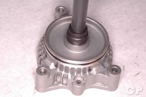
Pull out the bearing retainer with a bearing puller.


Remove the washer and spacer from the generator housing.


Press the seal out from the inside of the generator housing.
Coat the lips of the new seal in Suzuki "A" grease. Drive in a new seal.
Suzuki Super Grease "A": 99000-25030
Place the spacer and the washer in the housing.

Drive in a new bearing with a suitable bearing driver. Install the bearing retainer plate. Install the three bearing retainer plate screws with new O-rings and tighten them securely with a #2 Phillips screwdriver.


Inspect the rotor bearing. by turning it with a finger. the bearing should turn smoothly without noise or excessive play. Replace the bearing if needed.
Use a Bearing remover tool to remove the rotor bearing.
Special Tool- Bearing Remover: 09913-60910
Inspection
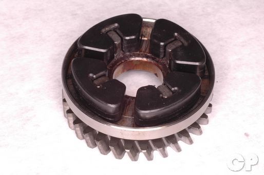
Inspect the driven gear and dampers for wear and damage.
Set your multimeter to read ohms of resistance and check for continuity between the stator wire leads as shown. Continuity should exist between the first lead and the other three. Replace the stator if continuity does not exist.
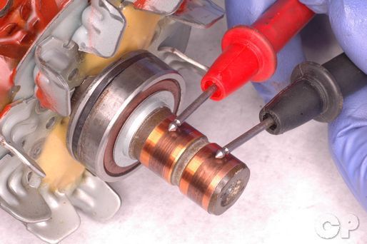
Check for continuity between the two slip rings on the rotor coil. Replace the rotor if continuity does not exist.


Inspect the slip rings on the end of the rotor. If the rings are dirty or corroded clean them up with 400 grit sand paper and wipe the clean with a dry lint free towel. Measure the outside diameter of the slip rings with a micrometer or vernier calipers.
(Slip Ring Diameter Service Limit: 14.0 mm or 0.55 in)
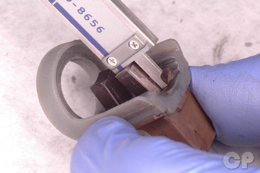
Measure the length the carbon brushes extend from their holder. Replace the brushes if they do not meet the service limit.
(Brush Length Service Limit: 4.5 mm or 0.18 in)
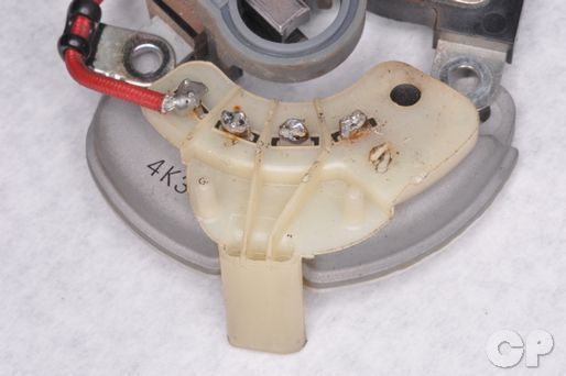
To inspect the rectifier first remove the red wire from its terminal with a soldering iron. Check for continuity between the four rectifier terminals amongst themselves and the bottom of the rectifier (ground). Switch the positive and negative meter leads and recheck. The multimeter should show continuity with the polarity of the meter leads one way and show no continuity the opposite way. Replace the regulator if this is not the case.
Connect the regulator to a variable DC power source, switch, voltage meter, and bulb as shown. With the power set to 12 V and the switch on the bulb should light up. With the power set to 14.5 V and the switch on the bulb shouldn't light. Replace the regulator if these conditions are not met.
Assembly


Install the expander ring so that its apex lines up with the chamfered spot on the bearing.
Apply a non-permanent thread locking agent to the bearing retainer plate screws. Install the three bearing retainer screws with new O-rings and tighten them securely with a #2 Phillips screwdriver.
Suzuki Thread Lock "1342": 99000-32050

Route the three stator coil wires through the plastic guide to their proper terminals on the rectifier.
Install the three regulator mounting screws and tighten them securely with a #2 Phillips screwdriver.

Solder the stator coil wire to their appropriate rectifier terminals. Install the rectifier terminal cover.

Install generator cover and the three generator cover nuts. Tighten the nuts to specification with an 8 mm socket.
Place the damper housing on the rotor shaft. Coat the dampers in Suzuki moly paste and install them into the damper housing.
Suzuki Moly Paste: 99000-25140
Place the generator driven gear on the rotor shaft. Make sure the tabs fit into the damper pieces. Place the washer and nut on the rotor shaft.
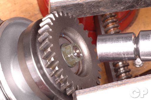
Hold the generator driven gear in a soft jawed vise and tighten the nut to specification.
(Generator Driven Gear Nut Torque: 60 N-m or 43.5 lb-ft)
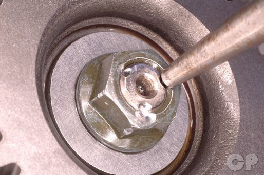
Stake the nut with a punch.
Installation
Apply Suzuki "A" grease to the generator O-ring. Install the generator into the engine.
Suzuki Super Grease "A": 99000-25030
Fit the generator driven gear into the crankcase.
Install the three generator mounting bolts and torque them to specification with a 12 mm socket.
(Generator Mounting Bolt Torque: 25 N-m or 18.0 lb-ft)
Install the countershaft sprocket cover. See the Countershaft Sprocket topic for more information.
Route the generator wires from the left side of the engine up to the base of the sub frame on the right side secure the wires along with the rest of the harness with wire bands.
Plug in the generator connector.

Secure the wires to the sub frame with wire bands.
Install the fuel tank. See the Fuel Tank topic for more information.
Install the fairings. See the Fairings topic for more information.
Copyright - Cyclepedia Press LLC

Note: If you are viewing this document offline be sure to visit the latest version online at http://www.cyclepedia.com before attempting any repairs. Updates are made without notice.